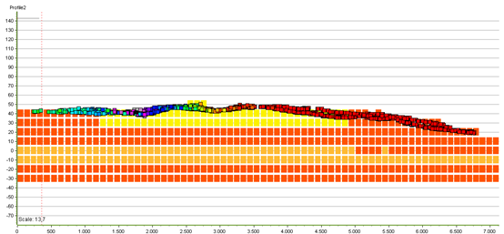
Cumulative Layer Thickness
This tutorial will guide you through the process of calculating the cumulative thickness through geological layers for particles grouped into traces using the ‘Cumulative Layer Thickness’ wizard.
Requirements
Data
The tutorial uses a terrain grid, geological layers or a voxel grid and particle traces grouped using IDs.
Step 1. Add your data
1. Check that your particle data setup is correct. The particles should be grouped into traces using an ID. You also need the coordinates, depth and a time stamp.
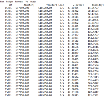
2. Open GeoScene3D and add the point database with the particle traces. See the tutorial Adding XYZ Points for more information. GeoScene3D should already contain a terrain grid, surface grids, geological layers and/or a voxel grid visualizing the geology.
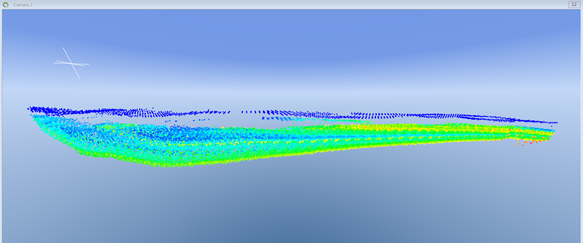
3. The file with the particle traces in this example is divided into to; All particle traces, and three randomly selected traces.
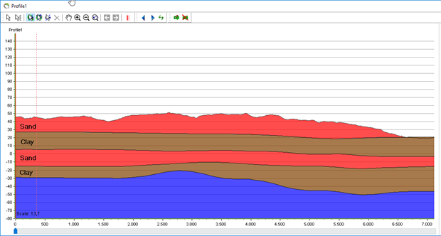
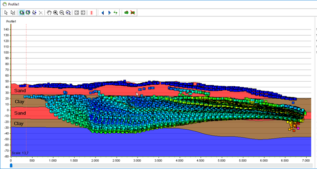
All particle traces:
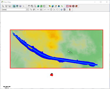
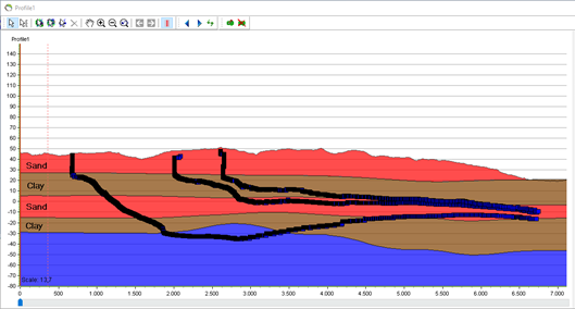
Three particle traces:
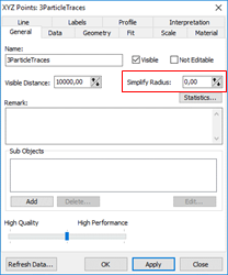
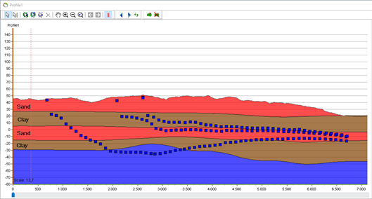
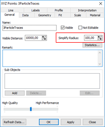
4. If your XYZ data is very detailed, you can change the visual appearance in GeoScene3D by setting the “Simplify radius” in the “Object Properties”. This will only affect the appearance in 3D/on profiles and maps, and not the actual calculation of cumulative layer thickness.
Step 2. Calculate the cumulative layer thickness using the geological layers.
1. Open the wizard.
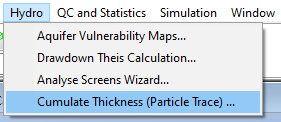
2. Press ‘Theme’ and ‘Layer Thickness Wizard’.
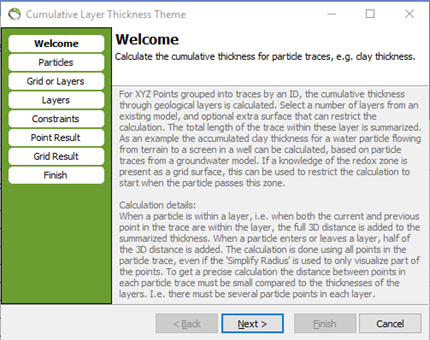
3. Press “Next” to go to the “Particle” page.
4. Choose the XYZ points with your particle traces.
5. Decide if you want the XYZ result placed in the starting point of the trace using the Z coordinate from the trace or from the terrain. Choosing the last option, you also have the possibility to add an offset from the terrain.
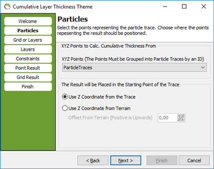
6. Press next to go to the “Grid or Layers” page
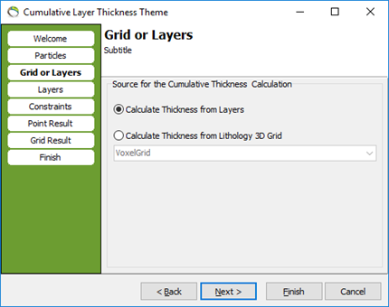
7. Choose if you want the calculation to use the geological layers or voxel grid. For now, we use the geological layers. Please go to step 4 to continue with the voxel grid.
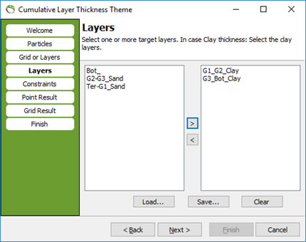
8. Press next to go to the “Layers” page. Select the layers for which the calculation will calculate the cumulated thickness. In this example we have chosen all the clay layrs.
9. You have the possibility to save your settings, so later you can reload the settings if needed.
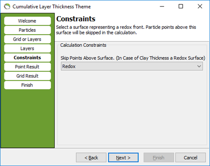
10. Press “Next”. Select a surface for which the particle points above will be skipped in the calculation. If you do not want this constraint, choose (none).
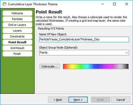
11. Press “Next”. Select a name for the result, the object group node and a color scale.
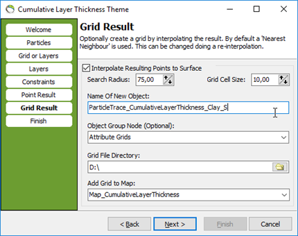
12. Press “Next”. Optionally create a grid by interpolating the result (recommended). The interpolated grid gives the best visualized result in GeoScene3D (using the map). By default, “nearest neighbor” is used. This can be changed doing a re-interpolation.
13. Choose a name, group node, file directory and if you want the grid result added to a map (recommended).
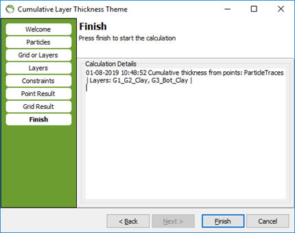
14. Press “Next”. You can now see the calculation details.
15. Press “Finish” and the calculation will start
16. When the calculation is done, GeoScene3D will ask for a place to save the database.
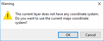
17. A warning pops up hence the new layer does not have any coordinate system. You can use the current coordinate system from the map by pressing OK.
Step 3. The result
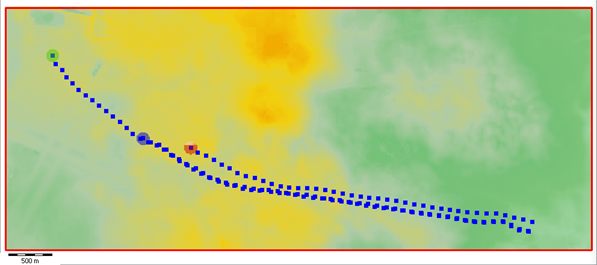
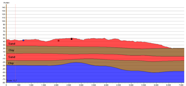
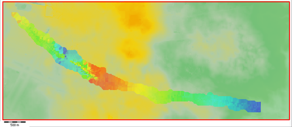
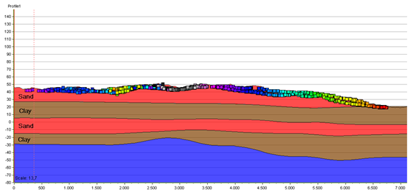
1. The result is visualized on the map (Step 9). For every particle trace the cumulative layer thickness is calculated and the result is interpolated into a 2D grid. The colors represent the cumulative thickness (in this case the cumulative clay layer thickness).
The result for the 3 particle traces:
2D grid on map:

XYZ database on profile (notice that the result is placed in the starting point of the trace using the Z coordinate):

The result for all particle traces:
2D grid on map:

XYZ database on profile (notice that the result is placed in the starting point of the trace using the Z coordinate):

Note:
GeoScene3D creates a 2D grid based on the calculation. This grid will appear in the Objects → Attribute Grids. The grid is used on the map and colored using the cumulative layer thickness, which in the grid is represented as the depth. This makes the grid only useful on the map, and not in the 3D space. The attribute grids are therefore automatically switched off, and not visible in 3D.

Step 4. Calculate the cumulative layer thickness using a voxel grid
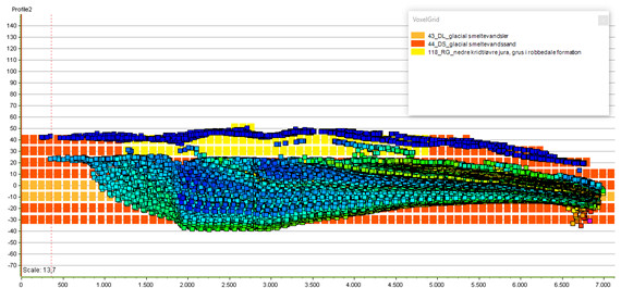
All particle traces:
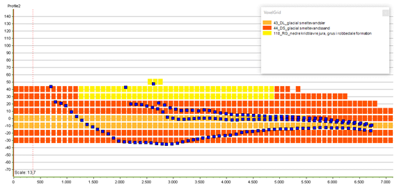
Three particle traces:
1. Follow step 2.1 to 2.7
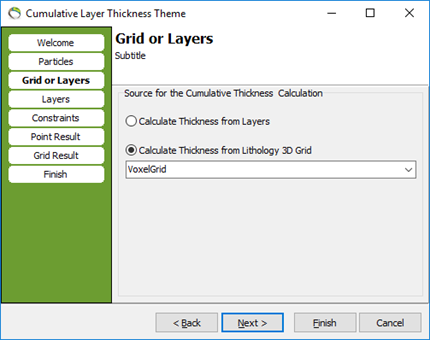
2. Choose the voxel grid.
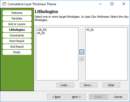
3. Press “Next”. Select the lithologies for which the calculation will calculate the cumulated thickness. In this example we have chosen the voxels containing clay.
4. You have the possibility to save your settings, so later you can reload the settings if needed.
5. Follow step 2.10 to 2.17.
Step 5. Result
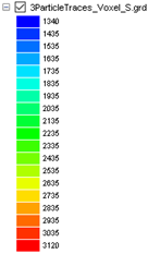
1. The result is visualized on the map (Step 9). For every particle trace the cumulative layer thickness is calculated and the result is interpolated into a 2D grid. The colors represent the cumulative thickness (in this case the cumulative clay layer thickness).
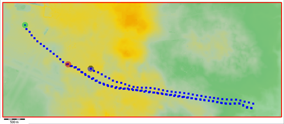
The result for the 3 particle traces:
2D grid on map:
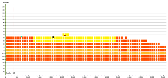
XYZ database on profile (notice that the result is placed in the starting point of the trace using the Z coordinate):

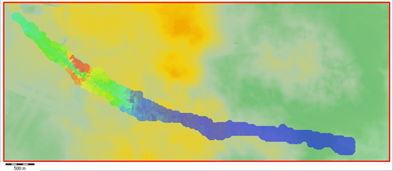
The result for all particle traces:
2D grid on map:
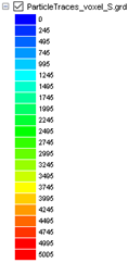
XYZ database on profile (notice that the result is placed in the starting point of the trace using the Z coordinate):
