Camera Animations
This tutorial will show how to create a movement path and how to use that movement path in a camera animation.
Requirements
Data
You can use any project, e.g., the project you created in the tutorial: Creating a New Project.
Step 1. Preparations
Step 2. Digitize Pat
1. Select the “Movement Path Digitizer Tool”  , from the main tool bar.
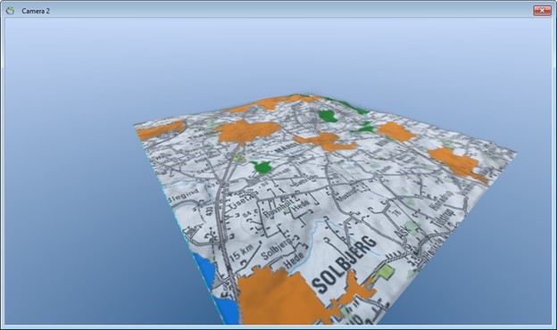
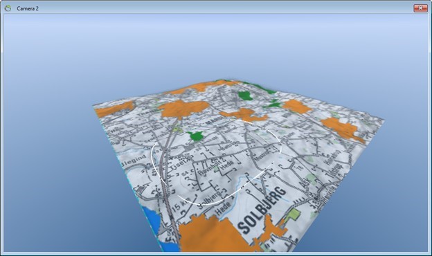
2. Click the terrain surface 5-6 times to digitize an arc shaped poly line on the surface approximately as show below.
3. Double-click the 3D Viewer and type in a name for the movement path, in this case Movement Path 1 and press the “OK” button.
4. Select the “Default Pointer Tool”  , in the main window toolbar.
Step 3. Drag Nodes
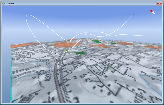
1. Zoom out a bit so that most of the nodes are visible in the 3D Viewer. Place the camera as it views down on the nodes with an angle of approximately 45 degrees from horizontal.
2. Carefully drag the nodes in the XY-plane with the mouse.
3. Press CTRL while dragging to move all nodes in the XY-plane.
4. Press ALT while dragging to move a single node vertically.
5. Press CTRL + ALT while dragging to move all nodes vertically.
Step 4. Create Camera Animation
1. Right click the “Objects” node in the Object Manager to show the context menu. Go to the “New Object” sub menu to the Animation sub menu and select “Camera Animation”.
2. Name the object “Camera Animation” in the “Name” edit box.
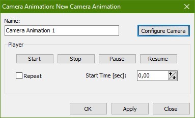
3. Press the “Configure Camera” button to show the “Animation Camera Settings” dialog.
4. Select the movement path you just created in the “Available Movement Paths” drop down list (there is probably only the one path that you just created) and press “OK”.
5. Press “OK” in the “Camera Animation” dialog.
Step 5. Try the Animation
1. Make the movement path invisible by off checking the check box for the movement path in the object manager.
2. Right-click the camera animation in the Object Manager, select Animation sub menu and select the “Start Animation” menu item - are you flying?
3. Press the red stop button in the main toolbar  , or right-click the camera animation node in the Object Manager, select Animation sub menu and select the “Stop Animation” menu item.
Step 6. Fly-By
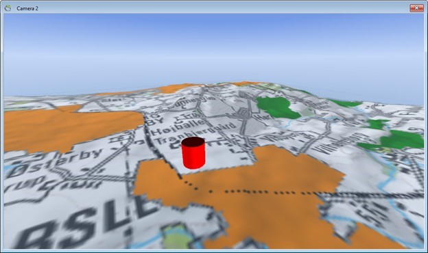
1. Right click the “Objects” node in the Object Manager to show the context menu. Go to the “New Object” sub menu, to the “3D Geometries” sub type and select “Vertical Cylinder”.
2. Name the object “Cylinder” in the “Name” edit box.
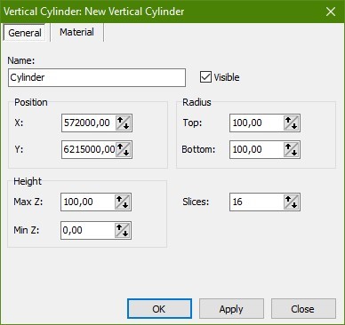
3. Set the position to X = 572000 and Y = 6215000.
4. Set “Top” and “Bottom” radius to 100.
5. Go to the “Material” tab and select red as color.
6. Press “OK” to close the dialog.
7. Double-click the camera animation node in the Object Manager to open “Object Properties”.
8. Press the “Configure Camera” button to open the “Animation Camera Settings” dialog.
9. Off check the “Align Direction” check box. Check the “Point Camera Towards Object” check box. Select the “Cylinder” in the “Available Objects” drop down list.
10. Press “OK” to close the dialog.
11. Restart the animation. The camera should point towards the cylinder.
Tip: If you do not want the cylinder in your animation, you can make it invisible in the “Object Properties” or by checking it off in the Object Manager.

