Add and Edit Interpretation Points in the Profile Window
This tutorial will show how to use the XYZ Points Editor Tool to edit XYZ points in the Profile Window and how to interpolate the XYZ points. This is a tutorial for advanced users and detailed instructions on how to add data is not provided for all object types.
Step 1. Start Edit Session
1. Open the Model.gsmod project from the Demo folder, right-click on profile 1 and select “Show Profile Window”. See the “Digitizing Profiles” tutorial for instructions on how to create a profile.
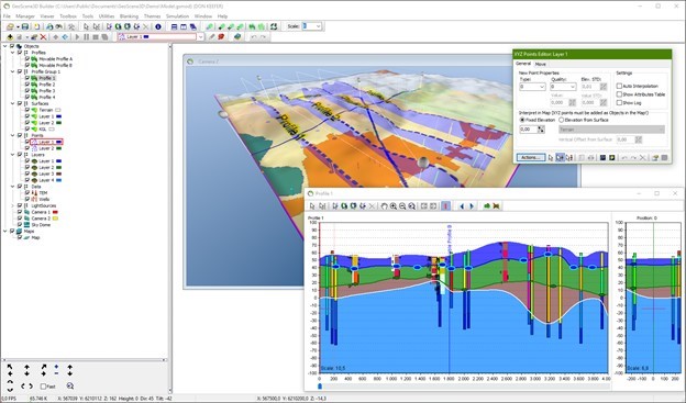
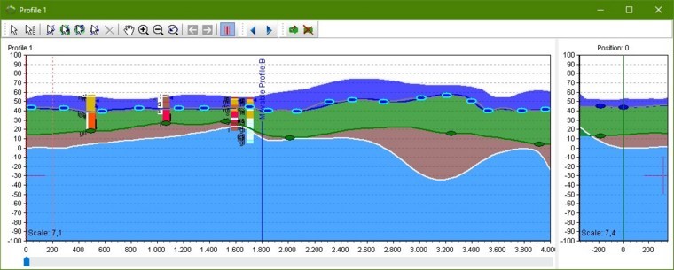
2. Select “Layer 1 (XYZ Points)” in the drop-down list in the editor toolbar. Click the “Start Editing Object” button to open the “XYZ Points Editor” tool window and to start an edit session, the profile window is illustrated in below image.
Step 2. Insert Points
1. Click the “insert new points tool” in the profile window.
2. When moving around in the profile window a cross appears with different colors which depends on the background color. To insert a point, press the CRTL button and the cross will turn red, click the mouse and a point is inserted. Alternatively press space-button to insert points.
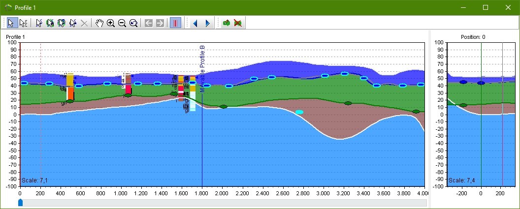
3. Try to insert a number of points in the profile window as illustrated in the below image. The inserted points will have a light blue color because they are selected.
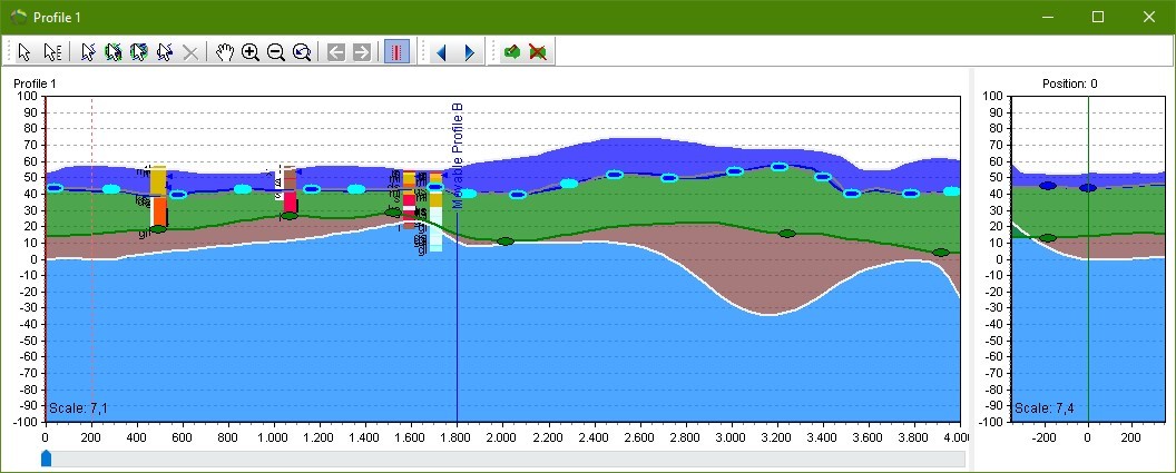
4. The inserted points are now recorded in the XYZ Points Attribute table as illustrated in below image.
5. In the XYZ Editor dialog, checkmark the Show Attributes Table and the XYZ Points attribute table opens.
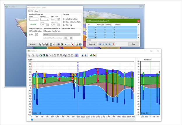
6. Functions of the “XYZ Points Attributes” is explained in the tutorial of “Editing XYZ Points - In 3D Window” Step 2.4.
Step 3. Interpolation
1. Click the “Interpolate” button  , in the XYZ Points Editor window to start the interpolation wizard.
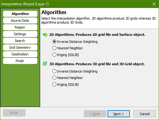
2. In the “Algorithm” page select the 2D “Inverse Distance Weighting” algorithm.
3. Go to the “Source Data” page. Press the “Get Data” button. Check the “Point Elevation” radio button and press “OK”. Tip: When a 2D interpolation algorithm has been selected this procedure is actually done automatically.
4. Go to the “Settings” page. Check that the “Exponent” is set to 2.
5. Go to the “Search” page. Set “Search Ellipsis” to 500 for both X and Y.
6. Go to the “Grid Geometry” page. In the “Grid Extent” box press the “Scene Extent” button to set grid size to scene extent. In the “Node Count” box set the node count to 200 for both “X” and “Y”. Try to change the node spacing and watch the Node count changing.
7. Go to the “Destination” page. Select a file name for the created grid, e.g., “[path]\XYZEditorGrid_profile.grd”. Enter “XYZEditorGrid_profile” in the “Name For Created Grid Dataset:” box. Enter “XYZEditorGrid_profile” in the “Name for Created Surface Object” box.
8. Go to the “Finish” page. Press “Finish” to perform the interpolation and to create a new surface object with associated dataset and source, the interpolated grid is illustrated with a light purple color in the below image.
Step 4. Select Points
1. Start or stay in the editing session.
2. Select the default pointer tool  , in the profile window.
3. CTRL+Click one of the dark blue points in the profile window to select it or draw a square with the mouse around one or more points. The color should change to a light blue to indicate that the point is now selected. You can now select the number of points you want. You can unselect all selected points by clicking an unselected point or clicking the “Unselect All Selected Points” button  .
.
Step 5. Move Points
1. Select the “Move The Selected Points” tool  , in the profile window.
2. If the text “Snapped” is flashing in the “XYZ Points Editor” window the selected point is snapped to an object and cannot be moved. To make the point movable the snap must be removed. Do this by selecting “Remove Snap…” in the “Actions…” menu or mark the point in the XYZ Points Attribute table, right-click and select “Remove snap…”. In this tutorial you must select an unsnapped and therefore movable point.
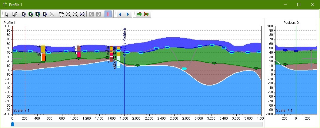
3. Now drag the selected point to Z = 0.
Step 6. Interpolate Again
1. Repeat step 3 to interpolate a new grid with the modified point position. Note: This time all the settings in the interpolation wizard is setup automatically. You may simply press “Destination” and check the radio button “Replace Existing Surface” and press “finish” to create the grid. Press “Yes” to confirm that you want to overwrite the existing grid. This interpolation is illustrated in below image with a purple color.
2. Insert new points or move points and interpolate these points.
