Edit 2D Grids
This tutorial will show how to use the Grid Editor Tool to edit 2D grids or surfaces. This is a tutorial for advanced users and detailed instructions on how to add data is not provided.
Requirements
Data
You can use any project that contains a surface e.g., the project you created in the tutorial: Creating a New Project.
Step 1. Preparations
1. Open your project.
2. Make the surface “Terrain” invisible.
3. Add the grid file “Editor.grd” as a surface object called “Surface” and give the grid an “elevation of good conductor” colorscale. See the
“Adding Surfaces” tutorial for instructions.
4. Add a Jupiter Wells object from “Jupiter.mdb” called “Jupiter Wells”. See the “Adding Wells” tutorial for instructions.
5. Add a Bitmap in the “New Map” window from “Terrain100K.bmp”, see the “Add Map Layers” tutorial for instructions.
6. Open the map “New Map”.
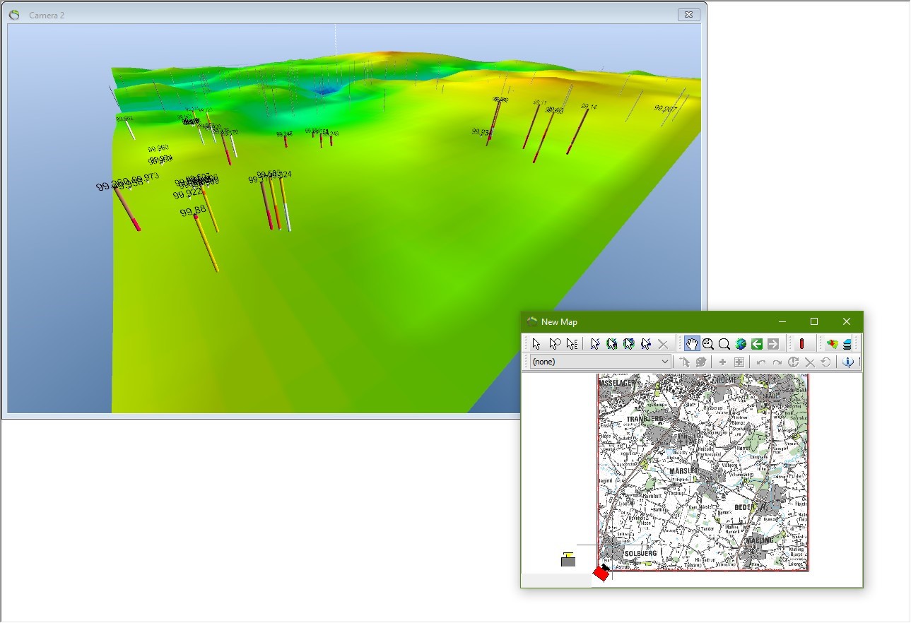
7. Move the camera to the lower left corner of the surface until the view looks approximately as in the image below.
Step 2. Start Edit Session
1. In the “Editor” toolbar  , select “Surface (Surface)” in the drop down list. Press the “Start edit session” button
  , to start an edit session. The “Grid Editor” tool window now open.
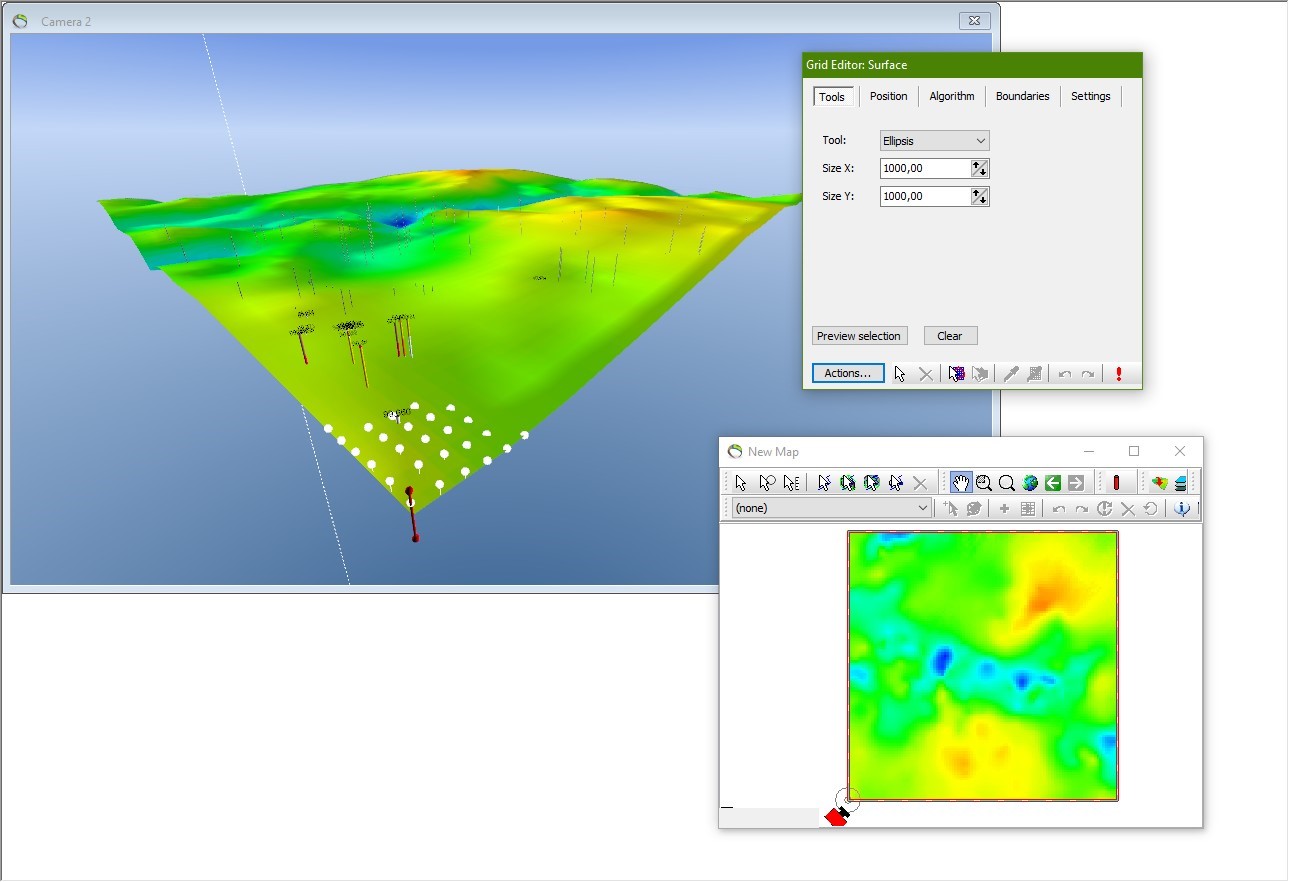
2. You will see a red pin and some white dots in the 3D window and a circle in the Map window, see image above. The dots form a preview of how the grid will look after the editing tool is applied. If not click the surface in the 3D or Map window while pressing the CTRL key.
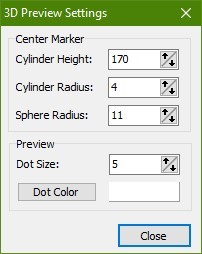
3. The tool center marker should now be visible as shown in above image, at the left-down corner in the 3D window. The settings of the 3D preview can be changed in the grid editor. Press the “Actions” button, select the “Tool Preview 3D Settings…”, change the values and close. The default values for the Tool preview settings are as illustrated in the below image and can be changed as what is convenient for the project.
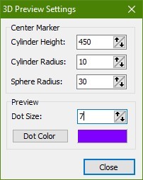
4. The Preview Settings is changed as illustrated in below image.
Step 3. Edit the Grid in the 3D Window
1. In the “Tools” tab in the “Grid Editor” dialog select “Ellipsis” in the “Shape” drop down list and set X- and Y-value to 1600.
In the “Algorithm” tab select “Gaussian” in the “Name” drop down list. Set “Variance” to 260 and “Scale” to 15000. Click the Preview Window in the “settings” tab to see how the shape of the Gaussian looks in 2D as illustrated in below image.
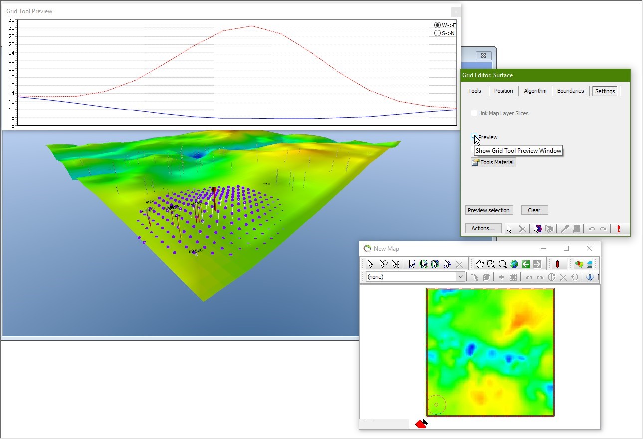
2. Click “Apply”  , in the Grid Editor box and watch the grid geometry change. The edit tool can be moved in 3D in 4 different ways as following:
- Dragging the center tool marker with white arrow button
- Using the arrow buttons in the “Grid Editor” dialog.
- Entering an exact XY position.
3. You can move and apply immediately current grid edit tool at a certain position using this button in toolbar 
4. Experiment with the use of different algorithms and geometries.
Step 4. Edit the Grid in the Map Window
1. In the same way as above in the 3D window you can move and apply the edit tool in the map window. Choose the same buttons in the Map Window. In the Map Window there is an extra editing tool where you can define a polygon you what to edit with Set Fixed Value or Add Fixed Value.
2. To digitize grid edit polygon, click the following button  , in the Grid Editor under Actions…
3. Digitize a polygon by clicking in the map as illustrated in image below.
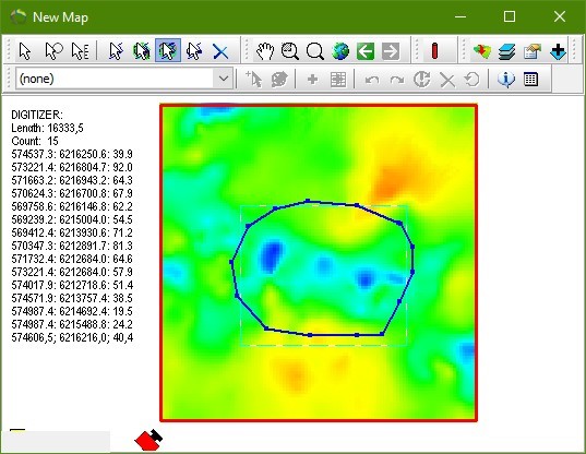
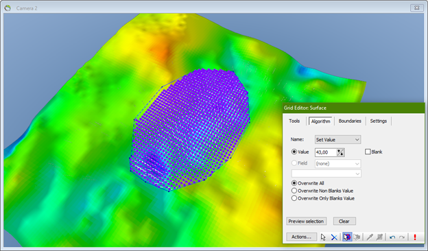
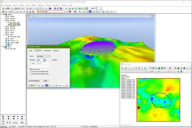
4. Click to apply the grid editor tool and subsequent click the red cross to clear digitized points from the screen. The edited polygon area will look as illustrated in the two below images. In the Grid Editor under the “Algorithm” tab check the “Overwrite All”. Adjust the value of the pins, here they are set to 43.
Step 5. Edit the Grid in the Map Window
1. Digitize a profile, see the “Digitizing profiles” tutorial for instructions.
2. Press the button  , “move current edit tool to clicked position” in the Profile Window.
3. Click apply  , in the Profile Window and watch the grid geometry change as illustrated in below image.
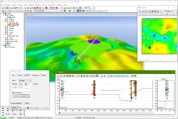
4. You can also use the button  , next to the
  , “move current edit tool to clicked position” button to move and apply current edit tool to clicked position as for the grid editing in the 3D window.
5. When only two handles are in use in the profile, the profile can be moved in several directions, see the “digitizing profiles” tutorial for instructions.
6. Experiment with the use of different algorithms and geometries.
Step 6. Save the Edited Grid
1. A snapshot of the edited grid may be saved at any time using the “Save Grid Snapshot” button and is also found under the “action” dropdown.
2. When you want to terminate the edit session press the “Stop Edit Session” button on the “Editor” toolbar (the pencil with a red stop sign). If you do not save the edits the grid will revert to the original state.
3. You can undo and redo steps in an edit operation using the arrows on the toolbar or the arrows below in the “grid editor” box.

