Importing 1D Geophysical Data from GeoSoft Files
This tutorial describes how to use the “Add Data Wizard” to import AEM data in the form of inverted 1D geophysical models from ASCII format GeoSoft files. The tutorial further explains how to import the associated data and how to create profile lines along flight lines.
Requirements
Data
1D geophysical GeoSoft files
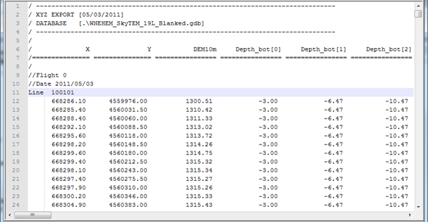
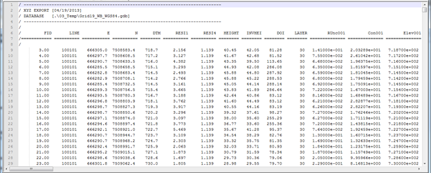
The figures show GeoSoft 1D geophysical model file example.
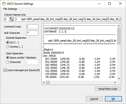
Above is shown two examples of GeoSoft 1D geophysical files from an AEM survey. The individual models are grouped in flight lines, and in the figure 1, line 11, the ‘Line 100101‘ shows the grouping parameter of the models. This format is called Line Interspersed. Another format of the GeoSoft file with flight lines can be as a separate column as seen in figure 2. GeoScene3D supports both formats.
The file consists of a general ‘header’ section and a ‘values’ section. Each line in the ‘values’ section of the file defines a geophysical 1D model with a number of layers. In figure 1 the depth to the bottom of the layer are in the written first, then the depths to the bottom of the layers, and at last the values, e.g. the resistivity. In figure 2 the value, conductivity, and the elevation to the top of the layers is next to each other. This means the conductivity is read in every third column.
Step 1.
1. Startup the “Add Data Wizard” by selecting the menu in “Manager” and select ”Add Data Wizard”, or by pressing the button  . This wizard guides you though several steps guiding you to the creation of a 3D object in GeoScene3D, an ODV model object. Furthermore there will be added a source and an ODV data set. The wizard steps are explained below.
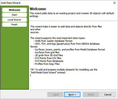
2. The wizard welcome screen. Press Next.
3. Select “Local File or Database”. Press Next.
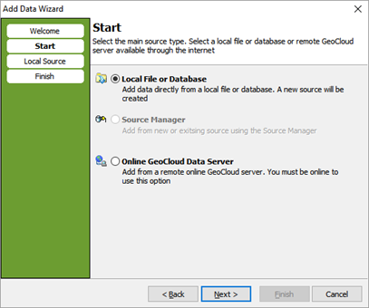
4. Browse the geosoft source for the ”1D geophysical layer data” on your hard drive or network. When selecting a GeoSoft file the window changes, and you have the opportunity to press “Source Settings”.
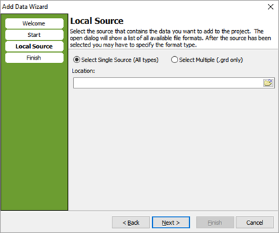
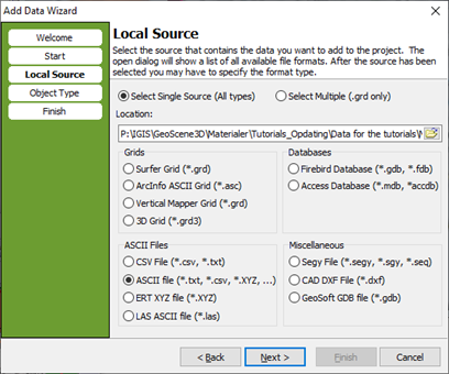
5. Change the ASCII Source Settings. See the tutorial: File Source Settings (GeoSoft). Press OK, and then press Next.
6. Select 1D Geophysical Models (One model per line, e.g. Geosoft format). Press Next.
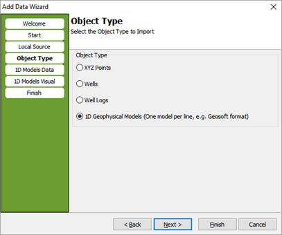
7. Setup the columns to be used. Press the ”Assign Fields” Button to access the column editor.
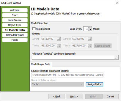
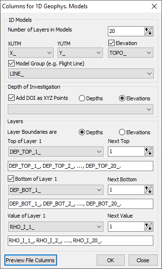
8. Match the position and layer info with Column names in the file, e.g. the ‘XUTM’ with the column named ‘X_’.
The Columns with XUTM, YUTM, depth/elevation to top of layer and value of layer 1 is mandatory.
The other columns with top of layer 2,3,…,19 (the number of layers) is specified by giving the columns between the tops in ‘Next Top’. For the example file in figure 1 the number is 1, whereas for figure 2 it is 3.
Here it is also possible to use a fixed geographical extent, instead of the current scene extent, and to add additional SQL selection criteria.
Use the ‘Preview Data’ or the ‘Preview File Columns’, to inspect the file. Note that the ‘Sort_Order_” and ‘Line_’ are now added as columns. Note that all columns are added an _ after the column name and also note that the brackets [ and ] is replaced by an underscore _
It is also possible to add the DOI. Check on the “Add DOI as XYZ Points” and choose if the values are depths or elevations.
When done press Next.

9. Select a Color Scale. It is also possible to automatically generate profiles along the model grouping index e.g. the flight lines. Please also write a profile group name. The profiles will only be generated is the data is in your scene extent.
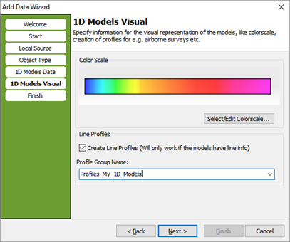
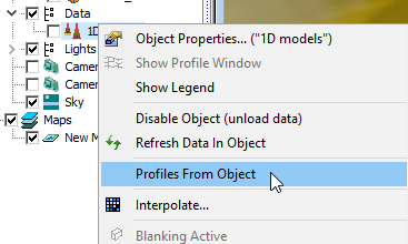
Please notice: The profiles will only be generated if the data coordinates are in your scene extent. If you would like to add the “Line Profiles” after importing the data (when moving the scene extent or if you did not check on this opportunity when importing), right-click the object in the object node tree and choose “Profiles from object”.
10. Name the 3D well object. You can select an existing group node or write the name of a new one. The well object will be places in this group.

Step 2. Result
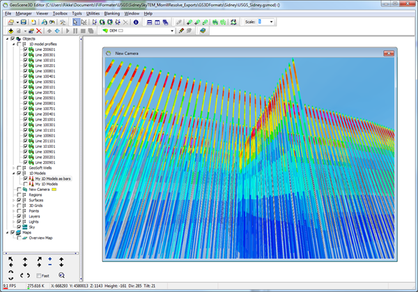
1. A new dataset has now been created in GeoScene3D, along with link to data sources and a new 3D object. Furthermore, a few profiles along the flight lines have been added to the project.
2. GeoSoft 1D geophysical model shown as fences.
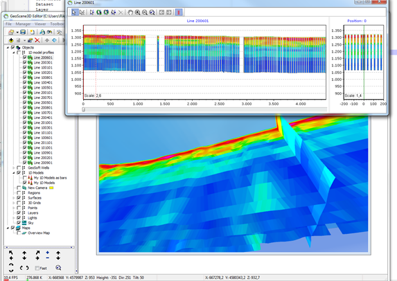
3. Using the wizard without creating the line profiles, gives as default the models shown as cylinders.
GeoSoft 1D geophysical model shown as cylinders.
